Pipe & Fittings
Fire Protection Technologies provides a full collection of pipe & fittings to suit our extensive range of products. Pipe and fittings used in Clean Agent System piping network must conform to the requirements as […]
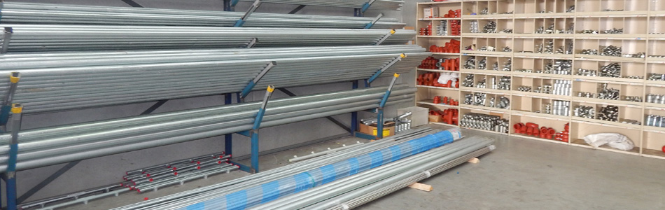
Fire Protection Technologies provides a full collection of pipe & fittings to suit our extensive range of products.
Pipe and fittings used in Clean Agent System piping network must conform to the requirements as outlined in ISO 14520, latest editions.
Piping materials, supports and spacing, must conform to the requirements as outlined in, ISO 14520. The thickness of the piping wall shall be calculated in accordance with ASME B31.1 Power PipingCode.
Caution: Cast iron pipe, steel pipe conforming to ASTM A120, or nonmetallic pipe SHALL NOT be used.
The following piping materials and configurations are acceptable:
- Schedule 40 Threaded, Welded & Grooved
- Schedule 80 Threaded & Welded
The following piping types and grades are acceptable for pipe configurations utilizing threaded, welded or grooved end connections:

FITTING MATERIALS
Fitting materials MUST conform to the requirements outlined in AS ISO 14520, latest edition.
| Fitting Size mm | Fitting Class |
| Up to 80 NPT | Class 300 malleable or ductile iron |
| Over 80 NPT | 1000 lb. ductile or forged steel |
| All pipe sizes | Class 300 flanged |
Note: All grooved fittings must be UL Listed and conform to the pressure requirements outlined in AS ISO 14520, latest edition.Cast Iron fittings are NOT acceptable.
PIPE SIZE CHANGE
Pipe size changes, to increase or decrease the size, can be done at three different locations in the piping network:
| Pipe Size Change at a Tee | When the change in pipe size is done at a tee, this is accomplished by using either a reducing tee or a standard tee and reducing fittings. All reducers must be concentric bell reducers or concentric reducing couplings. |
| Pipe Size Change at an Elbow | When the change in pipe size is done at an elbow, this is accomplished by using either reducing elbows or a standard elbow with concentric bell reducers or concentric reducing couplings. |
| Pipe Size Change at a Coupling | When the change in pipe size accomplished at a coupling, only concentric bell reducers or concentric reducing couplings can be used. |
Note: Reducing bushings, weld-o-let, and hole-cut fittings ARE NOT acceptable.
INSTALLATION
The piping system should be securely supported with due allowance for agent thrust forces, thermal expansion, and contraction, and should not be subject to mechanical, chemical, vibration, or other type of damage. The maximum horizontal spacing for screwed, welded or grooved pipe are as indicated on the following table:
| Pipe Size (MM) | Distance Between Supports (M) | Rod Diameter (MM) |
| 10 | 2.1 | 10 |
| 15 | 2.1 | 10 |
| 20 | 2.1 | 10 |
| 25 | 2.1 | 10 |
| 32 | 2.1 | 10 |
| 40 | 2.7 | 10 |
| 50 | 3.0 | 10 |
| 65 | 3.3 | 12 |
| 80 | 3.6 | 12 |
| 100 | 4.2 | 15 |
| 150 | 5.1 | 20 |
Notes:
• Each pipe section shall be cleaned internally before installation with a nonflammable cleaner such as Perchlorethylene in accordance with AS ISO14520, latest edition.
• Teflon® tape or joint compound shall be used on all threaded joints. All grooved coupling gaskets shall be lubricated per the manufacturer’s specifications.
• “C” Clamps are not acceptable to support rod hangers.
• Rigid pipe supports are required to support the “live load” of the pipe system during discharge. Rigid bracing is required at each directional change, fitting, tee and nozzle. All drops to 180° nozzles require back bracing in the opposite direction of the discharge. Earthquake bracing shall be used where required by local code. (Refer to ANSI B31.1 Power Piping Code for additional information)
• For additional information on pressure rating of pipe and fittings, plus recommended pipe supports and hangers, refer to FSSA’s Pipe Design Handbook, FSSA PDH-03.
• All system piping shall be installed in strict accordance to system plans. If piping changes are necessary, they must be recalculated on Fike’s Flow Calculation Program.
CONNECTION – CONTAINER TO PIPING NETWORK
The container discharge valve outlet is connected to the piping network using the following items:

Notes:
1) It is not necessary to supply a pipe union after the grooved coupling to facilitate removal of the container for service or maintenance purposes. The container can be removed by removing the grooved coupling provided with each container.
2) Adapter Nipple is supplied with 1/4” NPT female threads (plugged) to connect to:
• Discharge Pressure Switch
• Used to provide pressure to activate IVO (slave) container(s)

